Home>Products>Original hydraulic pump>R909441351 A7VO80LRH1/61R-PZB01-S REXROTH AXIAL-PISTON PUMP
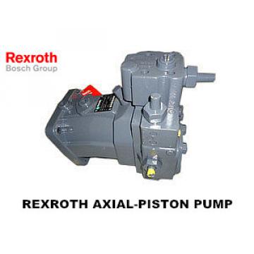
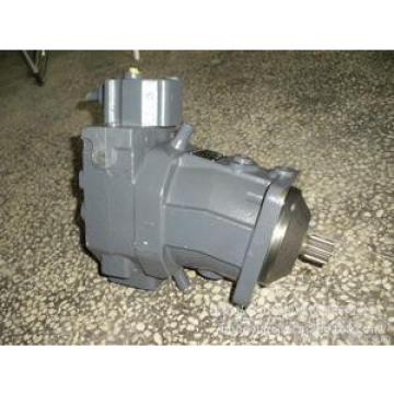
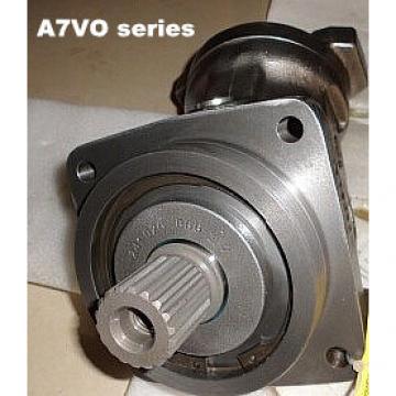
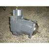
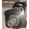
R909441351 A7VO80LRH1/61R-PZB01-S REXROTH AXIAL-PISTON PUMP
- Rexroth
R909441351 A7VO80LRH1/61R-PZB01-S
- Germany
- CE ISO
- 1pc
- contact us
- standrd package
- 5-7workdays
- T/T,Western Union
- 85pcs
-
 Anita Wu2020-07-10 09:46:19
Welcome to my shop! Glad to serve you! Please send your question!
Product Description
R900029353 A7VO80DRM/63R-PPB01
R900029354 A7VO107HD1/63R-NZB01
R900029637 A7VO80EP/63R-DZB01
R900030004 A7VO160LR/63R-NZB01
R900030043 A7VO160EP/63R-NZB01
R900031502 A7VO55LR/63R-NZB01
R900034085 A7VO160DR/63R-VZB01
R900040148 A7VO55EPG/63L-NPB01
R900049694 A7VO250LRD/63R-PZB01V
R900049709 A7VO500DR/63R-PPH01
R900050880 A7VO160HD2/63R-NZB01
R900051535 A7VO250HD1D/63L-PZB02
R900052318 A7VO250HD3D/63L-PZB02
R900052476 A7VO107LRH1/63R-NPB01
R900055250 A7VO80EP/63R-NPB01
R900056344 A7VO28LRD/63L-NZB01
R900058968 A7VO55EP/63R-NZB01
R900061939 A7VO160DR/63L-NZB01
R900072836 A7VO80LRD/63R-NZB01
R900075438 A7VO250EP1D/63R-PPB01
R900076107 A7VO80EP/63R-NZB01
R900078407 A7VO250DR/63R-VPB01
R900078408 A7VO107LRD/63R-VZB01
R900078409 A7VO55LRD/63R-VZB01
R900079131 A7VO107LR/63R-NPB01
R900080122 A7VO107EP/63R-NZB01
R900080866 A7VO500LRDH2/63R-PPH02
R900081735 A7VO107LR/63L-NZB01
R900084669 A7VO107LRH1/63L-NZB01
R900085434 A7VO107LRH2/63L-NPB01
R900087970 A7VO107LRG/63R-NZB01
R900088615 A7VO250HD1D/63R-PPB01
R900088894 A7VO80DRS/63R-NZB01
R900174891 A7VO107LR/63R-NZB01
R900200530 A7VO80DR/63L-VZB01
R900203795 A7VO160LRDH1/63R-NZB01
R900211585 A7VO55EP/63L-NPB01
R900213049 A7VO80LRG/63R-NPB01
R900214989 A7VO160LR/63R-NPB01
R900216614 A7VO80EPD/63R-NPB01
R900216738 A7VO250EP2D/63R-PPB01
R900218157 A7VO80LR/63R-NZB01
R900220891 A7VO250LRDH2/63R-PPB01
R900220958 A7VO80LRH1/63R-NPB01
R900226018 A7VO80DR/63R-NZB01
R900226083 A7VO107DR/63L-NPB01
R900226959 A7VO250LRD/63R-PPB01V
R900226991 A7VO107LRH5/63R-NPB01
R900231257 A7VO107DR/63R-VZB01
R900569478 A7VO250LRD/63R-PPB01
R900569969 A7VO55HD1/63R-NZB01
R900572027 A7VO55DR/63L-NPB01
R900990274 A7VO55HD1/63L-NZB01
R900991262 A7VO28HD2/63R-NZB01
R900991280 A7VO80EPG/63L-NPB01
R900991498 A7VO107HD2G/63R-NZB01
R900991602 A7VO28HD2/63L-NZB01
R900993817 A7VO250LRDN3/63R-VPB01
R902000134 A7VO160LRD/63R-NPB01
R902000135 A7VO107LR/63L-NPB01
R902000178 A7VO160LRH1/63R-NPB01
R902000179 A7VO107LRH1/63R-NPB01
R902000180 A7VO160HD2/63L-NZB01
R902000194 A7VO107LG2H5/63L-NZB01
R902000215 A7VO55EP/63R-VZB01
R902000223 A7VO160LR/63L-VZB01
R902000235 A7VO55LRH5/63L-NZB01
R902000264 A7VO160LG2H5/63L-NZB01
R902000296 A7VO80LRGH1/63R-NZB01
R902000354 A7VO160EP/63R-NPB01
R902000363 A7VO80LRDH2/63R-NPB01
R902000430 A7VO55DRG/63R-NPB01
R902000457 A7VO80LG2H5/63R-NZB01
R902000459 A7VO107LG2H5/63R-NZB01
R902000470 A7VO160LRDG/63R-NPB01
R902004003 A7VO160LRDH1/63L-NZB01
R902004046 A7VO160DR/63R-NPB01
R902004161 A7VO107LRH2/63L-NPB01
R902004167 A7VO55DR/63R-NPB01
R902004222 A7VO107LR/63R-NPB01
R902004278 A7VO55LR/63R-NPB01
R902004340 A7VO80DRG/63R-NPB01
R902004431 A7VO55LRH5/63R-NZB01
R902006517 A7VO107LRG/63R-NPB01
R902006527 A7VO107LRG/63R-NZB01
R902006683 A7VO107LRH2/63L-NZB01
R902006697 A7VO160LR/63L-NPB01
R902006723 A7VO107HD1G/63L-NZB01
Characteristic of R909441351 A7VO80LRH1/61R-PZB01-S
Variable displacement pump is equipped with axial conical piston rotor group designed with oblique shaft for hydrostatic transmission in open loop.
- used for walking machinery and fixed applications.
- the flow rate is proportional to the drive speed and displacement.
By adjusting the inclined shaft, the stepless change of flow can be realized.
- there are many kinds of control equipment to choose from.
Compact and firm pump with long service life.
Safety instructions of R909441351 A7VO80LRH1/61R-PZB01-S
- the A7VO pump is designed for open circuit.
- the project planning, installation and commissioning of the axial piston unit must be carried out by qualified personnel.
- read the corresponding instruction manual before using the axial piston unit. If necessary, you can obtain it from BOSCH Rexroth.
Axial plunger units (especially electromagnets) may be at risk of burning during and shortly after operation. Appropriate safety precautions should be taken, such as wearing protective clothing.
The characteristics of the axial piston unit may vary with different working conditions (working pressure, oil temperature).
- working line oil outlet:
Oil and fixed threads are designed for maximum pressure. The machine or system manufacturer must ensure that the safety factor of the connecting components and pipes meets the specified operating conditions (pressure, flow, hydraulic oil, temperature).
The service line and function port are only used for hydraulic piping.
- pressure shut-off valves and pressure controllers do not provide overvoltage safety protection. Overflow valve will be provided in hydraulic system.
- the data and instructions contained here must be followed.
- the product can not be approved as a component that follows the general mechanical safety concept of ISO 13849.
- use the following tightening torque:
• joint:
For fastening torque of the used joint, please contact us.
Installation bolts:
For installation bolts with ISO metric threads in accordance with DIN 13 and ASME B1.1, we recommend checking the fastening torque of each box according to VDI 2230.
• threaded hole of axial plunger unit:
The maximum allowable tightening torque MG Max is the maximum value for internal thread holes, and shall not exceed that value.
Locking screws:
For the metal locking screws provided with the axial piston unit, the fastening torque MV required for the locking screws should be used.
Installation instructions of R909441351 A7VO80LRH1/61R-PZB01-S
In the process of commissioning and operation, the axial plunger unit must always be filled with hydraulic oil and discharge air. These precautions must also be followed after a relatively long shutdown because the axial plunger unit may drain the hydraulic oil back into the tank through a hydraulic line.
Especially in the "transmission axis" installation position, oil injection and exhaust must be thoroughly carried out, otherwise there will be no oil operation and other dangers.
The shell drain chamber is internally connected to the oil suction cavity. No shell drain line is required between the shell and the fuel tank. Exceptions: For operations using pressure controllers or pressure shutoff valves, shell drain lines are required from nozzle T1 to tank.
In order to obtain a lower noise level, all the connecting pipes should be separated by elastic elements.
Under all operating conditions, the suction line and the shell drain line must go below the lowest oil level in the tank. During operation, the minimum oil suction pressure of the oil port S should not be reduced to 0.8 bar under the absolute pressure.
Thanks for your interesting~
Please tell me the bearing code number, dimension, drawing, or pictures?
How many sets want buy?
It will be help us confirm and offer to you correctly.
If you have any other inquiries welcome send me together.
we not only supply bearing,but also sell:oil seals,washer,lubricator,bearing ball,hydraulic pump and accessories.
Contact Us

- LOYAL MACHINERY PARTS COMPANY
- Email[email protected]
- AddressNathan 25-26, Tsimshatsui Kowloon Hongkong
- Phone(Working Time)00852-9518 9139
- WhatsApp+8615315583779
Related News
| Research on Electro-hydraulic Proportional Control Variable Mechanism of Axial Piston Hydraulic Pump |
| Self-adaptive Lubrication Characteristics of Conical Flow Distribution Pairs of Ball-piston Hydraulic Pumps |
| Modular Hydraulic Piston Pump Automatic Device |
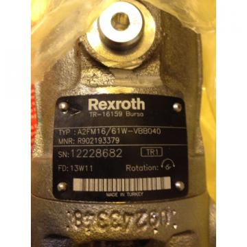 R902193379 A2FM16/61W-VBB040 REXROTH AXIAL-PISTON MOTOR
 40S CY 14-1B high pressure hydraulic axial piston Pump
 160YCY14-1B high pressure hydraulic axial piston Pump
 63YCY14-1B high pressure hydraulic axial piston Pump
 32MCY14-1B high pressure hydraulic axial piston Pump